Contents
Assignment updates
2023-11-30 Histograms are no longer marked here as optional. Added sysClkRateSet() to the example code.
Note
Your code should use sysClkRateSet() to increase the frequency frequency of the scheduler (i.e., rate of switching the tasks in the system). Both tasks (your code spawn) should use appropriate (larger than 200) priorities.
In addition, omit using I/O redirection when running your DKM, as the Workbench is not able to keep up connection alive. You can end the measurement by sending q in the serial terminal.
1 Assignment
A common task in real-time systems is to handle asynchronous events. In a computer, such events are usually represented by hardware interrupts. One of the most important parameter of a real-time computer system is so called interrupt latency and related scheduling latency, i.e. the time from when the event physically occurs to when an application task can handle it, either in an interrupt handler on in an application task. The latency depends on hardware, system load and other factors, but in a real-time operating system it should be bounded.
In this task, you will write a simple program to measure latencies of a Interrupt Service Routine (ISR) and of a Service Task triggered from the ISR. In a sense, you will write a VxWorks equivalent of Linux cyclictest utility.
You will use a hardware timer, available in our System-on-Chip (SoC), called Triple Timer Counters (TTC). The timer is basically a counter register, which the hardware automatically increments with certain rate. We will use the timer in so called interval mode. In this mode, when the incrementing register reaches some pre-configured value (called interval), the counter is reset to zero and an interrupt request (IRQ) is generated.
The following timing diagram shows various situations that can occur when an interrupt is handled in a multitasking operating system and how a hardware timer can be used to measure the corresponding latencies:
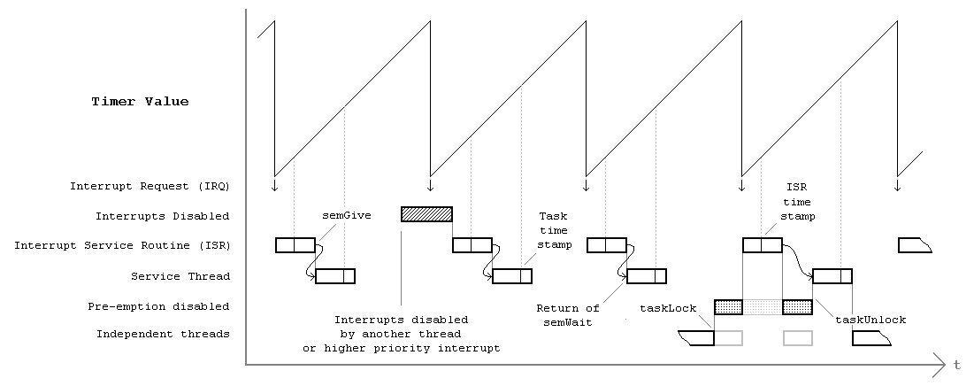
In the diagram, the first and the third IRQ is handled without delays: The ISR is executed right after the IRQ arrives and the service task (thread) takes control immediately after the ISR finishes (because the semaphore was released by the ISR). For the second IRQ, the ISR cannot be executed right after the IRQ because there was some other part of the operating system running (perhaps another ISR), which disabled the interrupts globally. This leads to delaying the execution of both the ISR and the service task. The fourth IRQ illustrates the case where some task disabled preemption. The ISR is executed right after the IRQ, however when the semaphore is released, the service task is not executed immediately because of the disabled preemption. This leads to delaying of the service task execution.
Since the IRQs are generated by the timer, we can easily measure the corresponding latencies by reading the timer's counter.
1.1 Solution guidelines
This project must be compiled as Downloadable Kernel Module, since we need direct access to registers of the hardware timer.
As a base for your code use a template shown on the bottom of this page.
Entry point function is called start. It will register the device driver for the TTC Timer and spawns all required tasks.
You need to write a simple low-level device driver for the hardware timer. See the hints below for source code examples. The driver will contain the Interrupt Service Routine (as seen in the diagram above). This routine will read and store the timer value (ISR Time Stamp) into the histogram and release the semaphore.
Service task (task named tService) will be released by the semaphore signaled from the ISR. After successful semTake, timer value (Task Time Stamp) will be read and stored into the histogram as well.
The monitoring task (task named tMonitor) will output the statistics from both measurements (the most interesting statistics is maximum; why?). Every second, it will print two numbers representing latencies in microseconds. An example output is shown below:
isr:5us task:24us
isr:5us task:24us
isr:7us task:24us
isr:7us task:24us
isr:15us task:33us
The main task (start()) will read input from the user. After pressing the q key, the program will terminate and print data for drawing the full histogram of measured latencies. One data for ISR latency, another for task scheduling latency. Each histogram bin will contain how many times the corresponding latency has been measured.
The output should be composed of three lines formatted as:
id=[val1,val2,val3,...]
The ids of the lines will be:
- idx: The following values will represent latencies of bins in units of timer tics. Note that if the timer is configured as recommended below, each bin represents 36 ns. Print only the bins where some latencies were measured, i.e., histogram counts are greater than zero.
- isr: The values will represent the counts of ISR latencies.
- tsk: The values will represent the counts of task latencies.
Example histogram data can look like this:
idx=[10,12,18,19,20,120]
isr=[1045,5368,12,1,0,0]
tsk=[0,0,18,125,6126,155,2]
Plot the histogram data to a figure. Horizontal axis should show latencies in microseconds. Vertical axis should be in log scale and should start at value smaller than 1 (e.g., 0.1) so that the latencies that occurred only once are also visible.
An example histogram is shown below.
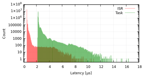
Investigate what happens to maximum latencies when you load the system by flooding board's network interface with the following command.
ping -s 64000 -i 0.2 <board_IP_addr>
1.2 Lab submission guidelines
In order to submit this assignment during the lab, please prepare:
- Maximum ISR and Task latencies in microseconds before and after pinging the board.
- Histogram of both measurements (IRQ→ISR and IRQ→Task) before and after pinging the board.
2 Hints
2.1 TTC timer registers
To program the hardware timer, you need to write to its registers. The registers are documented in Zynq-7000 Technical Reference Manual (TRM). The TTC timer is described in Section 8.5 and its registers in Appendix B.32.
To access the registers from a C program, we prepared several macros that simplify it and make the resulting code more readable:
#define CLOCK_RATE              1000

/* Offsets of each register from the base address (see TRM B.32) */
#define TTC_CLOCK_CTRL_OFS      0x00
#define TTC_COUNTER_CTRL_OFS    0x0c
#define TTC_COUNTER_VAL_OFS     0x18
#define TTC_INTERVAL_OFS        0x24
#define TTC_INTERRUPT_OFS       0x54
#define TTC_INTERRUPT_EN_OFS    0x60

/* Bitmaks and macros for setting of selected bits in some registers */
#define INTERRUPT_EN_IV         (1 << 0)
#define COUNTER_CTRL_DIS        (1 << 0)
#define COUNTER_CTRL_INT        (1 << 1)
#define CLOCK_CTRL_PRESCALE_EN  (1 << 0)
/* Macro for setting PS_VAL bits. If prescale is enabled, the count
 * rate is divided by 2^(N+1) */
#define CLOCK_CTRL_PRESCALE(N)  (((N) & 0xf) << 1)

/* Selects which of the three timers to user-error */
#define TIMER_OFFSET 0x0

/* Macros for timer register access */
#define TTC_CLOCK_CTRL(pTimer)      (*((volatile UINT32 *)((pTimer)->regs + TIMER_OFFSET + TTC_CLOCK_CTRL_OFS)))
#define TTC_COUNTER_CTRL(pTimer)    (*((volatile UINT32 *)((pTimer)->regs + TIMER_OFFSET + TTC_COUNTER_CTRL_OFS)))
#define TTC_COUNTER_VAL(pTimer)     (*((volatile UINT32 *)((pTimer)->regs + TIMER_OFFSET + TTC_COUNTER_VAL_OFS)))
#define TTC_INTERVAL(pTimer)        (*((volatile UINT32 *)((pTimer)->regs + TIMER_OFFSET + TTC_INTERVAL_OFS)))
#define TTC_INTERRUPT(pTimer)       (*((volatile UINT32 *)((pTimer)->regs + TIMER_OFFSET + TTC_INTERRUPT_OFS)))
#define TTC_INTERRUPT_EN(pTimer)    (*((volatile UINT32 *)((pTimer)->regs + TIMER_OFFSET + TTC_INTERRUPT_EN_OFS)))
To read or write a register, use the TTC_* macro with pTimer parameter, which contains a pointer to the base address (see below for how to obtain it). For example, to read the counter value use:
int val = TTC_COUNTER_VAL(pTimer);
To write to a register, e.g., to disable the counter, do:
TTC_COUNTER_CTRL(pTimer) = COUNTER_CTRL_DIS;
To write the timer driver, you will need to configure it via its registers and write an interrupt handler.
The purpose of individual registers and their selected bits with recommended settings is described below.
TTC_CLOCK_CTRL is the clock control register.
Because the timer counter is only 16 bit wide we have to set the prescaler to make the counter overflow less frequently:
- CLOCK_CTRL_PRESCALE_EN bit enables the prescaler.
- CLOCK_CTRL_PRESCALE(N) configures the prescaling. The input clock rate 111.111111 MHz will be divided 2^(N+1). For our purpose, a good value of clock rate is 27.7 MHz. With this rate, the counter will be incremented every 36 ns, which allows generating interrupts every 2.36 ms (for maximum value of TTC_INTERVAL) or faster.
TTC_COUNTER_CTRL is the counter control register. The bits we will use are:
- COUNTER_CTRL_DIS to disable (stop) the counter. When this bit is not set, the counter is enabled.
- COUNTER_CTRL_INT to use the counter in so called Interval mode, which allows generating interrupts periodically.
TTC_COUNTER_VAL register contains the the current value of the counter.
TTC_INTERVAL configures the maximum value that the counter will count to. Together with the prescaler, this value can be used to set IRQ frequency. See Choosing the timer period below.
TTC_INTERRUPT_EN register allows enabling different types of interrupts. We will need to enable so called Interval interrupts, with INTERRUPT_EN_IV bit.
TTC_INTERRUPT register signalizes, which interrupts are pending. Reading this register acknowledges the reception of the interrupt and clears the pending bits.
2.2 Interrupt handler
When writing the interrupt handler (also called interrupt service routine (ISR)) keep in mind that after the TTC generates the interrupt, and you read and store the timer value, you need to acknowledge the interrupt request to stop the hardware generating it. This is done by clearing (setting to zero) the corresponding bits in the interrupt register. The register has so called clear-on-read property, so to clear the bit reading the register as shown below is sufficient:
/* Read the interrupt register to acknowledge reception of the
 * interrupt (see TRM B.32) */
TTC_INTERRUPT(pTimer);
If you do not reset the interrupt, the processor appears as halted, because once you return from the interrupt handler, it will be immediately called again.
2.3 Choosing the timer period
One reaming question is what period to choose for our timer-generated IRQs. The proper value depends on the characteristic periodicity of system load, processor speed etc. Best results are obtained when the period is approximately two times the maximum expected latency. This makes it likely that we will detect all intervals when IRQs are disabled. A good value for our hardware is about 300 µs. Too small value will lead to timer overflow during long latencies; too big value will require longer measurements to detect the worst-case latency.
2.4 Driver skeleton
Below is a skeleton of the timer device driver. The entry point is the start() function. At the beginning, it registers the driver by calling vxbDrvAdd. You are supposed to replace all TODO lines.
#include "vxWorks.h"
#include <hwif/buslib/vxbFdtLib.h>
#include <hwif/vxBus.h>
#include <semLib.h>
#include <stdio.h>
#include <subsys/int/vxbIntLib.h>
#include <sysLib.h>
#include <taskLib.h>

#define CLOCK_RATE              1000

/* Offsets of each register from the base address (see TRM B.32) */
#define TTC_CLOCK_CTRL_OFS      0x00
#define TTC_COUNTER_CTRL_OFS    0x0c
#define TTC_COUNTER_VAL_OFS     0x18
#define TTC_INTERVAL_OFS        0x24
#define TTC_INTERRUPT_OFS       0x54
#define TTC_INTERRUPT_EN_OFS    0x60

/* Bitmaks and macros for setting of selected bits in some registers */
#define INTERRUPT_EN_IV         (1 << 0)
#define COUNTER_CTRL_DIS        (1 << 0)
#define COUNTER_CTRL_INT        (1 << 1)
#define CLOCK_CTRL_PRESCALE_EN  (1 << 0)
/* Macro for setting PS_VAL bits. If prescale is enabled, the count
 * rate is divided by 2^(N+1) */
#define CLOCK_CTRL_PRESCALE(N)  (((N) & 0xf) << 1)

/* Selects which of the three timers to user-error */
#define TIMER_OFFSET 0x0

/* Macros for timer register access */
#define TTC_CLOCK_CTRL(pTimer)      (*((volatile UINT32 *)((pTimer)->regs + TIMER_OFFSET + TTC_CLOCK_CTRL_OFS)))
#define TTC_COUNTER_CTRL(pTimer)    (*((volatile UINT32 *)((pTimer)->regs + TIMER_OFFSET + TTC_COUNTER_CTRL_OFS)))
#define TTC_COUNTER_VAL(pTimer)     (*((volatile UINT32 *)((pTimer)->regs + TIMER_OFFSET + TTC_COUNTER_VAL_OFS)))
#define TTC_INTERVAL(pTimer)        (*((volatile UINT32 *)((pTimer)->regs + TIMER_OFFSET + TTC_INTERVAL_OFS)))
#define TTC_INTERRUPT(pTimer)       (*((volatile UINT32 *)((pTimer)->regs + TIMER_OFFSET + TTC_INTERRUPT_OFS)))
#define TTC_INTERRUPT_EN(pTimer)    (*((volatile UINT32 *)((pTimer)->regs + TIMER_OFFSET + TTC_INTERRUPT_EN_OFS)))

// Data structure describing the timer device
struct psrTimer {
    VIRT_ADDR regs;
    VXB_RESOURCE *pResIrq;
};

// Interrupt Service Routine
static void timerIsr(struct psrTimer *pTimer)
{
    /* Read the interrupt register to acknowledge reception of the
     * interrupt (see TRM B.32) */
    TTC_INTERRUPT(pTimer);

    // Read the timer TTC_COUNTER_VAL(pTimer) and store the result.
    TODO_ISR

    // release the semaphore
    semGive(isrSemaphore);
}

LOCAL VXB_FDT_DEV_MATCH_ENTRY psrTimerMatch[] = {
    {"cvut,psr-ttc", NULL},     /* This should match the timer node in the Device Tree */
    {}                          /* Empty terminated list */
};

LOCAL STATUS timerProbe(VXB_DEV_ID pInst)
{
    STATUS st = vxbFdtDevMatch(pInst, psrTimerMatch, NULL);
    if (st == OK)
        printf("timerProbe %s\n", st == OK ? "OK" : "ERROR");
    return st;
}

LOCAL STATUS timerAttach(VXB_DEV_ID pInst)
{
    VXB_RESOURCE *pRes;
    struct psrTimer *pTimer = (struct psrTimer *)vxbMemAlloc(sizeof(struct psrTimer));
    if (pTimer == NULL) {
        perror("vxbMemAlloc");
        goto err;
    }

    vxbDevSoftcSet(pInst, pTimer);

    // Map the timer registers to memory
    pRes = vxbResourceAlloc(pInst, VXB_RES_MEMORY, 0);
    if (pRes == NULL) {
        fprintf(stderr, "Memory resource allocation error\n");
        goto err_timer;
    }

    /* Store register base address (where are the registers mapped) */
    pTimer->regs = ((VXB_RESOURCE_ADR *)(pRes->pRes))->virtAddr;

    VXB_RESOURCE *pResIrq;
    pResIrq = vxbResourceAlloc(pInst, VXB_RES_IRQ, 0);
    if (pResIrq == NULL) {
        fprintf(stderr, "IRQ resource alloc error\n");
        goto err_irq;
    }

    // TODO: Configure the timer registers
    TODO_CONFIG_TIMER_REGS

    // Connect the ISR and enable interrupts
    STATUS st;
    st = vxbIntConnect(pInst, pResIrq, timerIsr, pTimer);
    if (st == ERROR) {
        fprintf(stderr, "vxbIntConnect error\n");
        goto err_connect;
    }
    st = vxbIntEnable(pInst, pResIrq);
    if (st == ERROR) {
        fprintf(stderr, "vxbIntEnable error\n");
        goto err_int_en;
    }
    pTimer->pResIrq = pResIrq;  /* Remember the value for timerDetach() */

    return OK;

err_int_en:
    vxbIntDisconnect(pInst, pResIrq);
err_connect:
    vxbResourceFree(pInst, pResIrq);
err_irq:
    vxbResourceFree(pInst, pRes);
err_timer:
    vxbMemFree(pTimer);
err:
    return ERROR;
}

LOCAL STATUS timerShutdown(VXB_DEV_ID pDev)
{
    printf("timerShutdown\n");
    struct psrTimer *pTimer = vxbDevSoftcGet(pDev);
    if (pTimer == NULL) {
        fprintf(stderr, "No context in timerShutdown");
        return OK;
    }
    // Disable interrupts
    TTC_COUNTER_CTRL(pTimer) = COUNTER_CTRL_DIS;
    return OK;
}

LOCAL STATUS timerDetach(VXB_DEV_ID pDev)
{
    printf("timerDetach\n");

    struct psrTimer *pTimer = vxbDevSoftcGet(pDev);
    vxbIntDisable (pDev, pTimer->pResIrq);
    vxbIntDisconnect (pDev, pTimer->pResIrq);
    vxbResourceFree (pDev, pTimer->pResIrq);
    vxbMemFree(pTimer);

    return OK;
}

LOCAL VXB_DRV_METHOD timerMethods[] = {
    /* DEVICE API */
    {VXB_DEVMETHOD_CALL(vxbDevProbe), timerProbe},
    {VXB_DEVMETHOD_CALL(vxbDevAttach), timerAttach},
    {VXB_DEVMETHOD_CALL(vxbDevShutdown), timerShutdown},
    {VXB_DEVMETHOD_CALL(vxbDevDetach), timerDetach},
    VXB_DEVMETHOD_END};

// The main driver structure
VXB_DRV psrTimerDrv = {
    {NULL},                       /* Linked list header */
    "psr_ttc",                    /* Name */
    "VxBus Timer Driver for PSR", /* Description */
    VXB_BUSID_FDT,                /* Class */
    0,                            /* Flags */
    0,                            /* Reference count */
    timerMethods,                 /* Method table */
};

/*
 * serviceTask()
 *
 *  This function is spawned as a Service task with name `tService`.
 *
 *  Service task is running in a loop, waiting for `isrSemaphore` to
 *  be unlocked. After successfully taking this semaphore, timer value
 *  is read and stored into the histogram.
 */
void serviceTask(struct psrTimer *pTimer);

/*
 * Print ISR and task latency histograms
 *
 * Example output:
 *
 * idx=[10,12,18,19,20,120]
 * isr=[1045,5368,12,1,0,0]
 * tsk=[0,0,18,125,6126,155,2]
 */
void printHists();

/*
 * Prints maximum latencies encountered so far. Should be called every second.
 *
 * Example output:
 *
 * isr:15us task:33us
 */
void printStats();

void start()
{
    printf("Starting\n");
    sysClkRateSet(CLOCK_RATE);

    // Register our driver
    STATUS st = vxbDrvAdd(&psrTimerDrv);
    if (st == ERROR) {
        fprintf(stderr, "vxbDrvAdd failed\n");
        return;
    }

    // Get context pointer (pTimer) from the driver. You will need
    // to pass it to the service task.
    VXB_DEV_ID ttcDrv = vxbDevAcquireByName("psr_ttc", 0);
    if (ttcDrv == NULL) {
        fprintf(stderr, "vxbDevAcquireByName failed\n");
        return;
    }

    struct psrTimer *pTimer = vxbDevSoftcGet(ttcDrv);
    if (pTimer == NULL) {
        fprintf(stderr, "vxbDevSoftcGet returned NULL\n");
        return;
    }

    TODO_INIT_AND_RUN_THE_REST

    vxbDevRelease(ttcDrv);
    vxbDrvRemove(&psrTimerDrv);

    printHists();

    printf("Finished\n");
}
2.5 Device tree
The above driver skeleton calls several functions (vxbFdtDevMatch, vxbResourceAlloc, vxbIntConnect/Enable) which read information about hardware configuration from the Device Tree. Device Tree is a data structure describing the hardware the VxWorks kernel runs on. It is passed to the kernel by the bootloader. The source code of the Device Tree for our board is shown below and is also available in the BSP at /opt/psr/mzapo-image/xlnx_zynq7k_3_0_0_1/zynq-mzapo.dts. Notice that the node with the psr_ttc label has the same compatible value as our code above and that the node contains information about the base address of timer registers and used interrupts. This information is what the above mentioned functions read.
You don't need to add the Device Tree anywhere into your project. The bootloader is already configured correctly to use it.
/* zynq-mzapo.dts - Xilnx ZYNQ-7000 MZAPO device tree source */

/*
 * Copyright (c) 2015-2017, 2019, 2021 Wind River Systems, Inc.
 * Copyright (c) 2022 Michal Sojka
 *
 * This file is licensed under the Creative Commons CC0 1.0 Universal Public
 * Domain Dedication License (CC0-1.0). You may obtain a copy of the License
 * at:
 *     https://creativecommons.org/publicdomain/zero/1.0/
 * Unless required by applicable law or agreed to in writing, software
 * distributed under the License is distributed on an "AS IS" BASIS,
 * WITHOUT WARRANTIES OR CONDITIONS OF ANY KIND, either express or implied.
 */

/dts-v1/;
#include "zynq-7000.dtsi"

/ {
        chosen {
                bootargs = "gem(0,0) f=0x40";
        };

        amba {
                uart0: uart@e0000000 {
                        compatible = "xlnx,xuartps";
                        current-speed = <115200>;
                        reg = <0xE0000000 0x1000>;
                        clock-frequency = <50000000>;
                        interrupts = <59>;
                        interrupt-parent = <&intc>;
                };
                uart1: uart@e0001000 {
                        status = "disabled";
                };
                ttc_1: ps7-ttc@f8002000 {
                        /*
                         * Don't let VxWorks drive the second TTC. We
                         * will use it with our driver (see below)
                         */
                        status = "disabled";
                };
                psr_ttc: psr-ttc@f8002000 {
                        compatible = "cvut,psr-ttc";
                        reg = <0xf8002000 0x1000>;
                        clock-frequency = <111111111>;
                        interrupt-parent = <&intc>;
                        interrupts = <69 70 71>;
                };
                motor1: pmod1@43c20000 {
                        compatible = "cvut,psr-motor";
                        /* Register locations */
                        reg = <0x43c20000 0x1000>, /* FPGA (PWM control, IRC status) */
                              <0xE000a000 0x1000>; /* GPIO (IRC IRQ) */
                        interrupt-parent = <&intc>;
                        interrupts = <52>;
                        gpio-irq-bit = <0x04>;
                };
                motor2: pmod2@43c30000 {
                        compatible = "cvut,psr-motor";
                        /* Register locations */
                        reg = <0x43c30000 0x1000>, /* FPGA (PWM control, IRC status) */
                              <0xE000a000 0x1000>; /* GPIO (IRC IRQ) */
                        interrupt-parent = <&intc>;
                        interrupts = <52>;
                        gpio-irq-bit = <0x40>;
                };
        };
};
