Contents
Assignment updates
2024-01-11 Submission guidelines are stored here.
2023-12-07 - After creating your team in BRUTE (motor) upload URL of your git repository (inside a text file) to git2.
1 Assignment
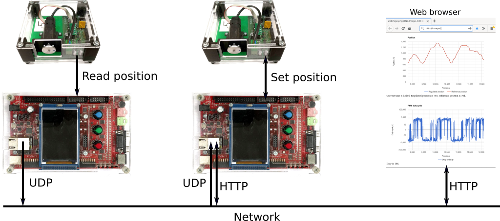
The goal of the semestral work is to create a digital motor controller. Your program will control the position of the motor according to the set-point given by the position of another motor, moved by hand (steer-by-wire). The set-point will be transferred between the two motor controllers using UDP messages. The actual state of the controller and its history will be published as live graphs over the HTTP protocol.
1.1 Instructions
Work in couples.
Create a team by selecting your teammate in the BRUTE system.
Use version control system GIT.
We expect commits from both of you in the repository. It is advised to host the repository at FEL GitLab. For more information see this page.
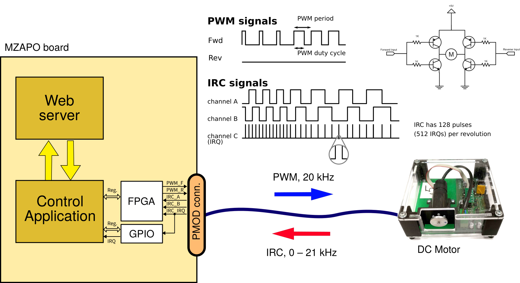
Implement a device driver with an interrupt handler for reading the motor position.
Motor position can be determined by decoding the IRC sensor signals. These signals are called A, B (phase-shifted A) and IRQ. The last signal can generate interrupts each time one of the A / B signals changes.
Implement a function for rotating the motor.
Motor can be rotated by generating PWM signals on board output pins. PWM signal can be generated by writing to FPGA registers (see below). Configure PWM frequency to 20 kHz.
Implement a PID controller to control the shaft position.
You can read more about the PID controller at Wikipedia. However, for your semestral work, you don't have to use the complete PID controller. Even a basic P controller is good enough.
Implement UDP communication from one board to another¹.
For network communication between the boards, your code from previous assignment can be reused. It is recommended to use standard BSD sockets API.
Implement a simple web server for displaying live graphs of the motor¹.
Live graphs served from the web server should display at least:
- actual motor position (absolute value),
- requested position (absolute value), and
- current PWM duty cycle (in range –100%, +100%).
The graphs should show at least 2 seconds of history with time resolution ≤ 5 ms.
Note ¹: Instructions marked with ¹ are not mandatory for a “low-point” solution.
2 Assessment
Semestral work assessment comprises the following independently assessed parts:
2.1 Motor control program (max. 18 points)
| Item | Points |
|---|---|
| IRC reading through interrupts (proper implementation without losing position) | 1* |
| Hardware generated PWM at 20 kHz | 0.5* |
| No busy-waiting, properly selected sampling period for motor | 0.5* |
| P(ID) or better controller (no ad-hoc solution) | 1* |
| Quality of regulation (no oscillations, fast response, minimal steady state error, ...) | 0 – 2 |
| Set-point specification (choose one of the following): | * |
| — From second motor through UDP communication | 6 |
| — From terminal via keyboard | 1 |
| Controller "debugging" (choose one of the following): | * |
| — Web page with live graphs | 7 |
— ASCII "bargraph" of action value (PWM width). Something like: -0.5 .....=====|.......... |
1 |
Note: Rows marked by * represent the minimum for “zápočet”.
2.2 Use of version control system (max. 4 points)
You have to use Git, a distributed version control system. See the instructions for using Git on our server. There will be two check dates:
- December 6, 2023 (for Wednesday labs) / December 7, 2023 (for Thursday labs), and
- when submitting the work.
We will evaluate the items from the table below.
| Item (evaluation date) | Points |
|---|---|
| Project is maintained using Git (1,2) | 0* |
| At least one commit every week (1,2) | 1 |
| Commit messages accurately describe the content of the commit (2) | 0.5 |
| Content of each commit is reasonable in its size (i.e., minimal) (2) | 0.5 |
| No generated files or binary files (e.g. .o, .pdf) are added in the repository (2) | 1 |
It is required that both persons from the team have commits in the repository.
Note: Rows marked by * represent the minimum for “zápočet”.
2.3 Programmer's documentation (max. 3 points)
- The goal is to learn tools that generate the documentation automatically from the source code (e.g. Doxygen or Sphinx + Breathe), not to write novels or learn how to create nice documents in LaTeX.
- Do not modify the generated documentation, e.g., to insert figures. Have all the documentation, including the text description and references to figures, in your source code.
- Look at example documentation created with Doxygen and the corresponding source code. Text-based part of the documentation is contained in file CANR_16X.H.
The documentation should contain:
| Item | Points |
|---|---|
| Short textual description of the application in the introduction (or on the main HTML page). | 0.5 |
| Instructions for compiling and running your application. | 0.5 |
| Screenshot of your web-based (or text-based) user interface | 0.5 |
| Data-Flow Diagram of your application i.e. how individual components (e.g. IRQ handler, controller, web-server) exchange data. Note: You need to draw this picture yourself; Doxygen cannot generate it automatically. | 1 |
| Description of global functions and variables (created by you) including the description of function parameters and return values. | 0.5 |
In order to submit your documentation, upload a generated PDF file to BRUTE, doc - Motor documentation assignment. However, expect that we may generate the documentation ourselves, awarding points only according to our version.
3 Hints
3.1 Things to avoid
(you should know why from lectures)
- Calling blocking functions (e.g. printf()) in interrupt handlers.
- Using floating point operations in interrupt handlers.
3.2 Working with floating point numbers
You must include the VX_FP_TASK option when creating a task that does any of the following:
- Performs floating-point operations.
- Calls any function that returns a floating-point value.
- Calls any function that takes a floating-point value as an argument.
For example:
tid = taskSpawn ("tMyTask", 90, VX_FP_TASK, 20000, myFunc, 2387, 0, 0, 0, 0, 0, 0, 0, 0, 0);
Some routines perform floating-point operations internally. The VxWorks documentation for each of these routines clearly states the need to use the VX_FP_TASK option.
3.3 Basic information
- Schematics of motor electronics
- Zynq-7000 Technical Reference Manual (TRM)
- Motor information, encoder (IRC) information. Our motor has an encoder with 128 pulses (512 IRQs) per revolution.
- Source code of a Linux driver for the motor (for inspiration – the driver was created for older PowerPC MPC5200 boards and would not work with current MZAPO boards)
3.4 FPGA registers
This section describes hardware registers that you can use to control the motors. These registers are implemented in the FPGA, which is a part of the Zynq chip. The motor can be connected to PMOD1 or to PMOD2 connectors. The set of registers for both connectors is the same, only the base address is different. Base addresses are:
- 0x43c20000 for the PMOD1 connector
- 0x43c30000 for the PMOD2 connector
You don't need to deal with these addresses directly in your program, because they are specified in the device tree and the driver skeleton (see below) reads them from there via vxbResourceAlloc().
The address of the register is the sum of the above base address and an offset from tables below.
Control Register (CR) [RW] offset 0x0000 |
|
| bit 6 | PWM_ENABLE – PWM Generator Enable
|
| bit 5 | PWM_R_DIRECT – Direct Control of PWM R Output |
| bit 4 | PWM_F_DIRECT – Direct Control of PWM F Output |
Status Register (SR) [RO] offset 0x0004 |
|
| bit 10 | IRC_IRQ_MON – actual value of IRC IRQ signal (note that for generating the IRQ, this signal is also connected to the GPIO inputs; see below) |
| bit 9 | IRC_B_MON – actual value of IRC input B |
| bit 8 | IRC_A_MON – actual value of IRC input A |
PWM Period Setup Register (PWM_PERIOD) [RW] offset 0x0008 |
|
| bit 29..0 | Period of PWM generated waveform in multiples of 10 ns (clock 100 MHz). Maximum possible period is about 5 sec. The register can be rewritten asynchronously even when PWM is enabled; If the new period is shorter than the actual period, it is shortened immediately. |
PWM Duty Control Register (PWM_DUTY) [RW] offset 0x000C |
|
| bit 31 | DUTY_DIR_R – request negative polarity of output voltage
|
| bit 30 | DUTY_DIR_F – request positive polarity of output voltage
|
| bit 29..0 | DUTY – PWM duty cycle, i.e. the number of 10 ns intervals to hold output active in every period. If set during ongoing period before the output is reset to zero the new value is applied immediately. |
3.5 Register access macros
To access the registers, we recommend using the following macros:
// GPIO registers (TRM sect. 14 and B.19)
#define GPIO_DATA_RO_OFFSET    0x068
#define GPIO_DIRM_OFFSET       0x284
#define GPIO_INT_EN_OFFSET     0x290
#define GPIO_INT_DIS_OFFSET    0x294
#define GPIO_INT_STATUS_OFFSET 0x298
#define GPIO_INT_TYPE_OFFSET   0x29c
#define GPIO_INT_POL_OFFSET    0x2a0
#define GPIO_INT_ANY_OFFSET    0x2a4

// FPGA registers (https://rtime.felk.cvut.cz/psr/cviceni/semestralka/#fpga-registers)
#define FPGA_CR_OFFSET      0x0
#define FPGA_CR_PWM_EN      0x40

#define FPGA_SR_OFFSET      0x0004
#define FPGA_SR_IRC_A_MON   0x100
#define FPGA_SR_IRC_B_MON   0x200
#define FPGA_SR_IRC_IRQ_MON 0x400

#define FPGA_PWM_PERIOD_OFFSET  0x0008
#define FPGA_PWM_PERIOD_MASK    0x3fffffff

#define FPGA_PWM_DUTY_OFFSET    0x000c
#define FPGA_PWM_DUTY_MASK      0x3fffffff
#define FPGA_PWM_DUTY_DIR_A     0x40000000
#define FPGA_PWM_DUTY_DIR_B     0x80000000

#define REGISTER(base, offs) (*((volatile UINT32 *)((base) + (offs))))

#define FPGA_CR(motor)         REGISTER((motor)->fpgaRegs, FPGA_CR_OFFSET)
#define FPGA_SR(motor)         REGISTER((motor)->fpgaRegs, FPGA_SR_OFFSET)
#define FPGA_PWM_PERIOD(motor) REGISTER((motor)->fpgaRegs, FPGA_PWM_PERIOD_OFFSET)
#define FPGA_PWM_DUTY(motor)   REGISTER((motor)->fpgaRegs, FPGA_PWM_DUTY_OFFSET)
#define GPIO_DIR(motor)        REGISTER((motor)->gpioRegs, GPIO_DIRM_OFFSET)
#define GPIO_INT_STAT(motor)   REGISTER((motor)->gpioRegs, GPIO_INT_STATUS_OFFSET)
#define GPIO_INT_EN(motor)     REGISTER((motor)->gpioRegs, GPIO_INT_EN_OFFSET)
#define GPIO_INT_DIS(motor)    REGISTER((motor)->gpioRegs, GPIO_INT_DIS_OFFSET)
#define GPIO_INT_TYPE(motor)   REGISTER((motor)->gpioRegs, GPIO_INT_TYPE_OFFSET)
#define GPIO_INT_POL(motor)    REGISTER((motor)->gpioRegs, GPIO_INT_POL_OFFSET)
#define GPIO_INT_ANY(motor)    REGISTER((motor)->gpioRegs, GPIO_INT_ANY_OFFSET)
#define GPIO_RAW(motor)        REGISTER((motor)->gpioRegs, GPIO_DATA_RO_OFFSET)

// Motor driver data
struct psrMotor {
    VIRT_ADDR fpgaRegs;
    VIRT_ADDR gpioRegs;
    UINT32 gpioIrqBit;
};
3.6 IRC sensor IRQ handling
To reliably calculate motor position be decoding IRC signals, it is necessary to handle the IRQs generated by motor. For that, one needs not only to use the registers described above, but also configure GPIO interrupts, because the FPGA delivers motor interrupts via GPIO. The code below shows a skeleton of the device driver that registers an interrupt service routine (motorIsr) to the hardware IRQ generated by the motor hardware.
The driver structure is the same as in our scheduler latency measurment. The device tree source, that has the information about how is the motor connected is shown there too. You can use the following probe and attach driver methods.
LOCAL VXB_FDT_DEV_MATCH_ENTRY psrMotorMatch[] = {
    {"cvut,psr-motor", NULL},
    {} /* Empty terminated list */
};

LOCAL STATUS motorProbe(VXB_DEV_ID pInst)
{
        if (vxbFdtDevMatch(pInst, psrMotorMatch, NULL) == ERROR)
                return ERROR;
        VXB_FDT_DEV *fdtDev = vxbFdtDevGet(pInst);
        /* Tell VxWorks which of two motors we want to control */
        if (strcmp(fdtDev->name, "pmod1") == 0)
                return OK;
        else
                return ERROR;
}

void motorISR(struct psrMotor *pMotor);
// Don't forget to acknowledge the interrupt in the handler by:
// GPIO_INT_STAT(pMotor) = pMotor->gpioIrqBit;


LOCAL STATUS motorAttach(VXB_DEV_ID pInst)
{
    struct psrMotor *pMotor;

    VXB_RESOURCE *pResFPGA = NULL;
    VXB_RESOURCE *pResGPIO = NULL;
    VXB_RESOURCE *pResIRQ = NULL;

    pMotor = (struct psrMotor *)vxbMemAlloc(sizeof(struct psrMotor));
    if (pMotor == NULL) {
        perror("vxbMemAlloc");
        goto error;
    }

    // Map memory for FPGA registers and GPIO registers
    pResFPGA = vxbResourceAlloc(pInst, VXB_RES_MEMORY, 0);
    pResGPIO = vxbResourceAlloc(pInst, VXB_RES_MEMORY, 1);
    if (pResFPGA == NULL || pResGPIO == NULL) {
        fprintf(stderr, "Memory resource allocation error\n");
        goto error;
    }

    pMotor->fpgaRegs = ((VXB_RESOURCE_ADR *)(pResFPGA->pRes))->virtAddr;
    pMotor->gpioRegs = ((VXB_RESOURCE_ADR *)(pResGPIO->pRes))->virtAddr;

    pResIRQ = vxbResourceAlloc(pInst, VXB_RES_IRQ, 0);
    if (pResIRQ == NULL) {
        fprintf(stderr, "IRQ resource alloc error\n");
        goto error;
    }

    int len;
    VXB_FDT_DEV *fdtDev = vxbFdtDevGet(pInst);
    const UINT32 *pVal = vxFdtPropGet(fdtDev->offset, "gpio-irq-bit", &len);
    if (pVal == NULL || len != sizeof(*pVal)) {
        fprintf(stderr, "vxFdtPropGet(gpio-irq-bit) error\n");
        goto error;
    }
    pMotor->gpioIrqBit = vxFdt32ToCpu(*pVal);
    printf("gpioIrqBit=%#x\n", pMotor->gpioIrqBit);

    /* Associate out psrMotor structure (software context) with the device */
    vxbDevSoftcSet(pInst, pMotor);

    // Configure GPIO
    GPIO_INT_STAT(pMotor) |= pMotor->gpioIrqBit; /* reset status */
    GPIO_DIR(pMotor) &= ~pMotor->gpioIrqBit;     /* set GPIO as input */
    GPIO_INT_TYPE(pMotor) |= pMotor->gpioIrqBit; /* generate IRQ on edge */
    GPIO_INT_POL(pMotor) &= ~pMotor->gpioIrqBit; /* falling edge */
    GPIO_INT_ANY(pMotor) &= ~pMotor->gpioIrqBit; /* enable IRQ only on one pin */

    // Connect the interrupt handler
    STATUS s1 = vxbIntConnect(pInst, pResIRQ, motorISR, pMotor);
    if (s1 == ERROR) {
        fprintf(stderr, "vxbIntConnect error\n");
        goto error;
    }
    // Enable interrupts
    if (vxbIntEnable(pInst, pResIRQ) == ERROR) {
        fprintf(stderr, "vxbIntEnable error\n");
        vxbIntDisconnect(pInst, pResIRQ);
        goto error;
    }

    GPIO_INT_EN(pMotor) = pMotor->gpioIrqBit;

    return OK;

error:
    // Free any allocated resources
    if (pResIRQ != NULL) {
        vxbResourceFree(pInst, pResIRQ);
    }
    if (pResGPIO != NULL) {
        vxbResourceFree(pInst, pResGPIO);
    }
    if (pMotor != NULL) {
        vxbMemFree(pMotor);
    }
    return ERROR;
}
When implementing motorShutdown method, don't forget disable generation of interrupts:
GPIO_INT_DIS(pMotor) |= pMotor->gpioIrqBit;
3.7 Web server
3.7.1 Skeleton of a simple web server
Example of communication between WWW browser and server
Web server skeleton:
#include <sys/types.h>
#include <sys/socket.h>
#include <netinet/in.h>
#include <netdb.h>
#include <stdio.h>
#include <sockLib.h>
#include <string.h>

#define SERVER_PORT     80 /* Port 80 is reserved for HTTP protocol */
#define SERVER_MAX_CONNECTIONS  20

void www()
{
    int s;
    int newFd;
    struct sockaddr_in serverAddr;
    struct sockaddr_in clientAddr;
    socklen_t sockAddrSize;

    sockAddrSize = sizeof(struct sockaddr_in);
    bzero((char *)&serverAddr, sizeof(struct sockaddr_in));
    serverAddr.sin_family = AF_INET;
    serverAddr.sin_port = htons(SERVER_PORT);
    serverAddr.sin_addr.s_addr = htonl(INADDR_ANY);

    s = socket(AF_INET, SOCK_STREAM, 0);
    if (s < 0) {
        printf("Error: www: socket(%d)\n", s);
        return;
    }

    if (bind(s, (struct sockaddr *)&serverAddr, sockAddrSize) == ERROR) {
        printf("Error: www: bind\n");
        return;
    }

    if (listen(s, SERVER_MAX_CONNECTIONS) == ERROR) {
        perror("www listen");
        close(s);
        return;
    }

    printf("www server running\n");

    while (1) {
        /* accept waits for somebody to connect and the returns a new file descriptor */
        if ((newFd = accept(s, (struct sockaddr *)&clientAddr, &sockAddrSize)) == ERROR) {
            perror("www accept");
            close(s);
            return;
        }

        /* The client connected from IP address inet_ntoa(clientAddr.sin_addr)
           and port ntohs(clientAddr.sin_port).

           Start a new task for each request. The task will parse the request
           and sends back the response.

           Don't forget to close newFd at the end */
    }
}
3.7.2 Using fdopen() to generate server responses
The easiest way to generate webserver responses is to use fdopen() function to “convert” the file descriptor returned by accept() to a FILE pointer. Then you can use all standard libc functions such as printf() to generate the response. For example:
FILE *f = fdopen(newFd, "w");
fprintf(f, "HTTP/1.0 200 OK\r\n\r\n");
fprintf(f, "Current time is %ld.\n", time(NULL));
fclose(f);
If you want to parse the request, e.g. to generate different responses for different URLs, we recommend the code snippets below. Both work around a bug in VxWorks I/O buffering.
If you care only about the first request line, use:
FILE *f = fdopen(newFd, "r+");
setvbuf(f, NULL, _IONBF, 0); /* Disable buffering to work around VxWorks bug */
char filename[100], http_ver[10];
int ret = fscanf(f, "GET %99s %9s\n", filename, http_ver);
if (ret != 2) {
        fprintf(stderr, "www: Request reading error\n");
        // ...
}
printf("GET %s %s\n", filename, http_ver);

setvbuf(f, NULL, _IOFBF, BUFSIZ); /* Reenable buffering */
fprintf(f, "HTTP/1.0 200 OK\r\n\r\n");
fprintf(f, "Requested file %s at time %ld.\n", filename, time(NULL));
fclose(f);
If you want to read the whole request with all HTTP headers, you can use:
FILE *f = fdopen(newFd, "r+");
char req_line[1000];
do {
        if (fgets(req_line, sizeof(req_line), f) == NULL) {
                perror("www: fgets");
                break;
        }
        rstrip(req_line);
    printf("len: %02d, req: %s\n", strlen(req_line), req_line);
    //break; // if this is here, the GET line is incorrectly printed by the fprintf below due to a VxWorks bug!
} while (req_line[0] != 0);
fprintf(f, "HTTP/1.0 200 OK\r\n\r\n");
fprintf(f, "Current time is %ld.\n", time(NULL));
fclose(f);
3.7.3 How to refresh a web page periodically?
There are many ways. One is to use javascript code in the onload attribute of the body element as in the example below. This example reloads the page approximately every 100 milliseconds and shows actual time in milliseconds.
<html>
  <head>
    <title>Test</title>
  </head>
  <body onload="setTimeout(function(){location.reload()}, 100);">
    <script>document.write(Date.now());</script>
  </body>
</html>
3.7.4 Drawing graphs as SVG
Look at this example for how to include SVG graphics in the html page.
3.7.5 Serving static files
The easiest way to serve static files such as index.html is to define their contents as a string constant in your program (e.g. static const char *index_html) and send it to the client with fprintf(f, "%s", index_html) as shown above.
To generate such a string constant you can use an online converter or shell command xxd -i index.html.
3.8 FAQ
Q: Why do not I receive any characters from keyboard in my program?
A: VxWorks shell "eats up" entered characters. Type exit to quit the shell.
